
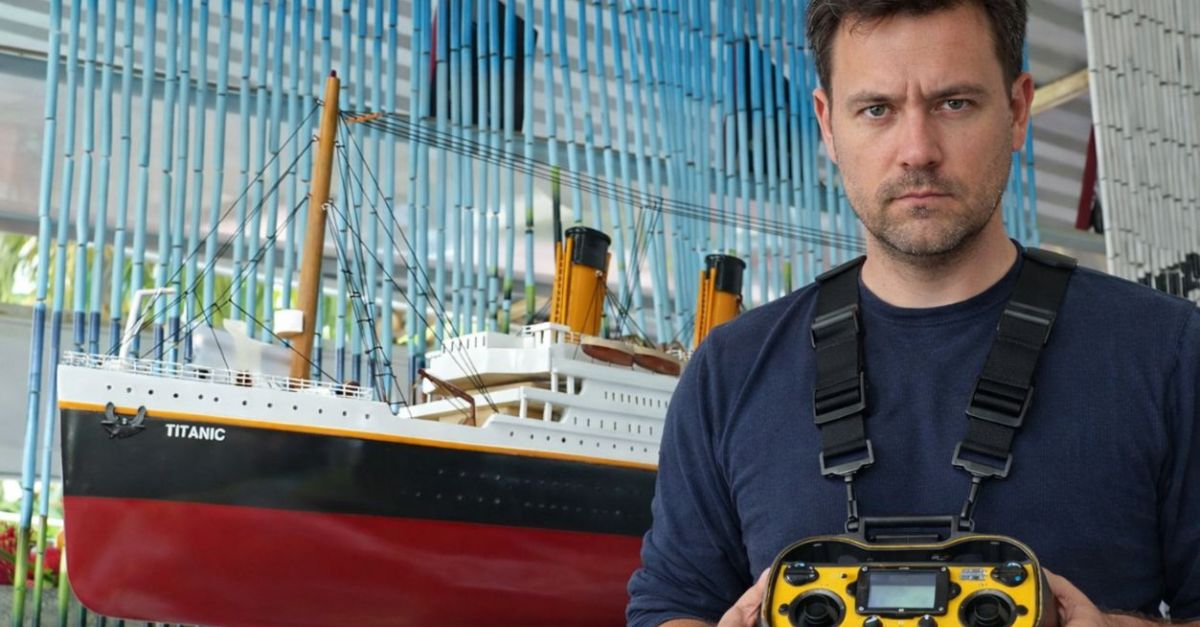
It’s Finally Out
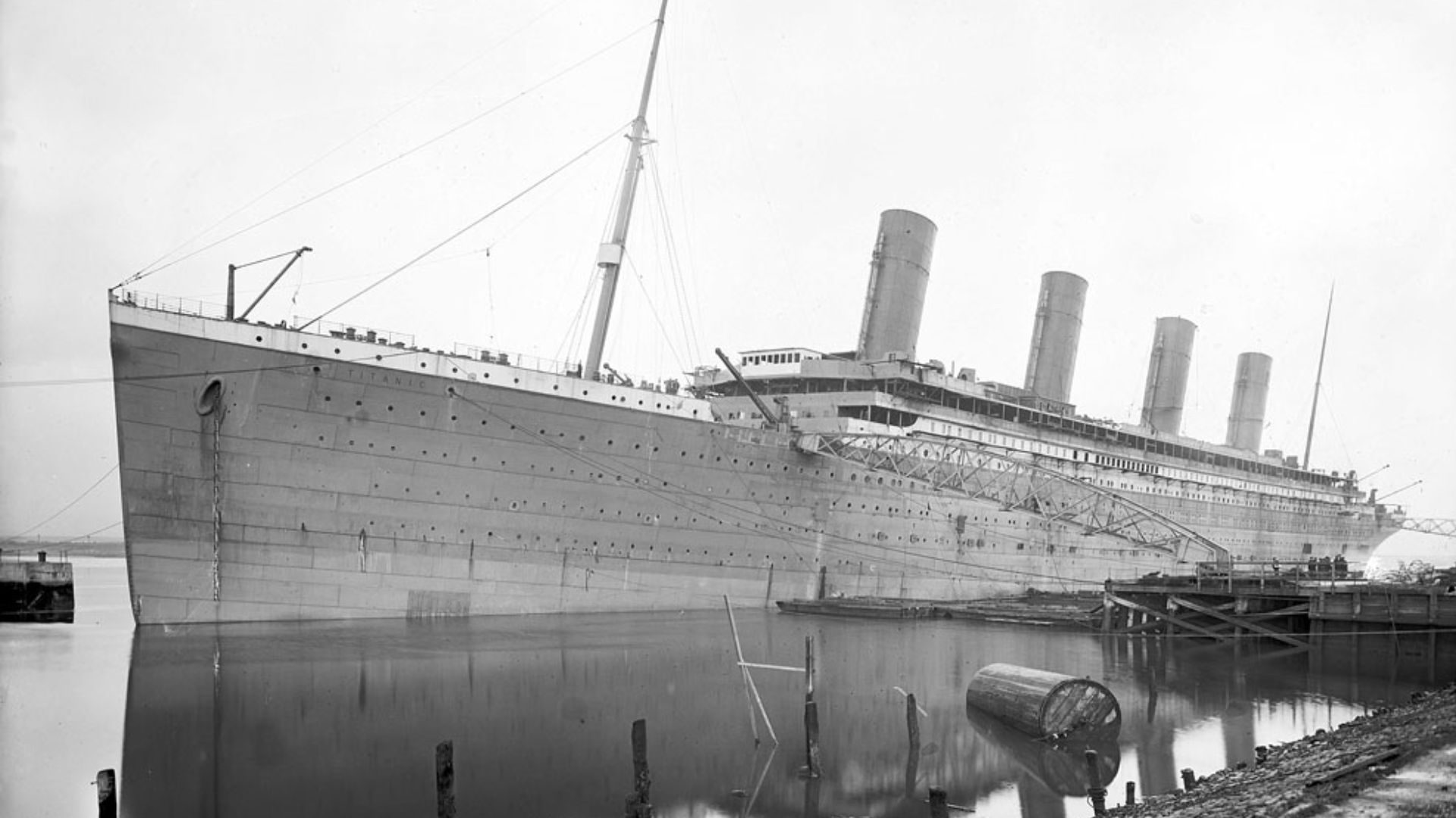
Remote-operated vehicles descended nearly 2.5 miles into darkness. Submersible-mounted cameras revealed Titanic’s colossal machinery, frozen on the seafloor where the ship broke apart, capturing structures that human divers could never reach or survive.
 Prenn, Wikimedia Commons, Modified
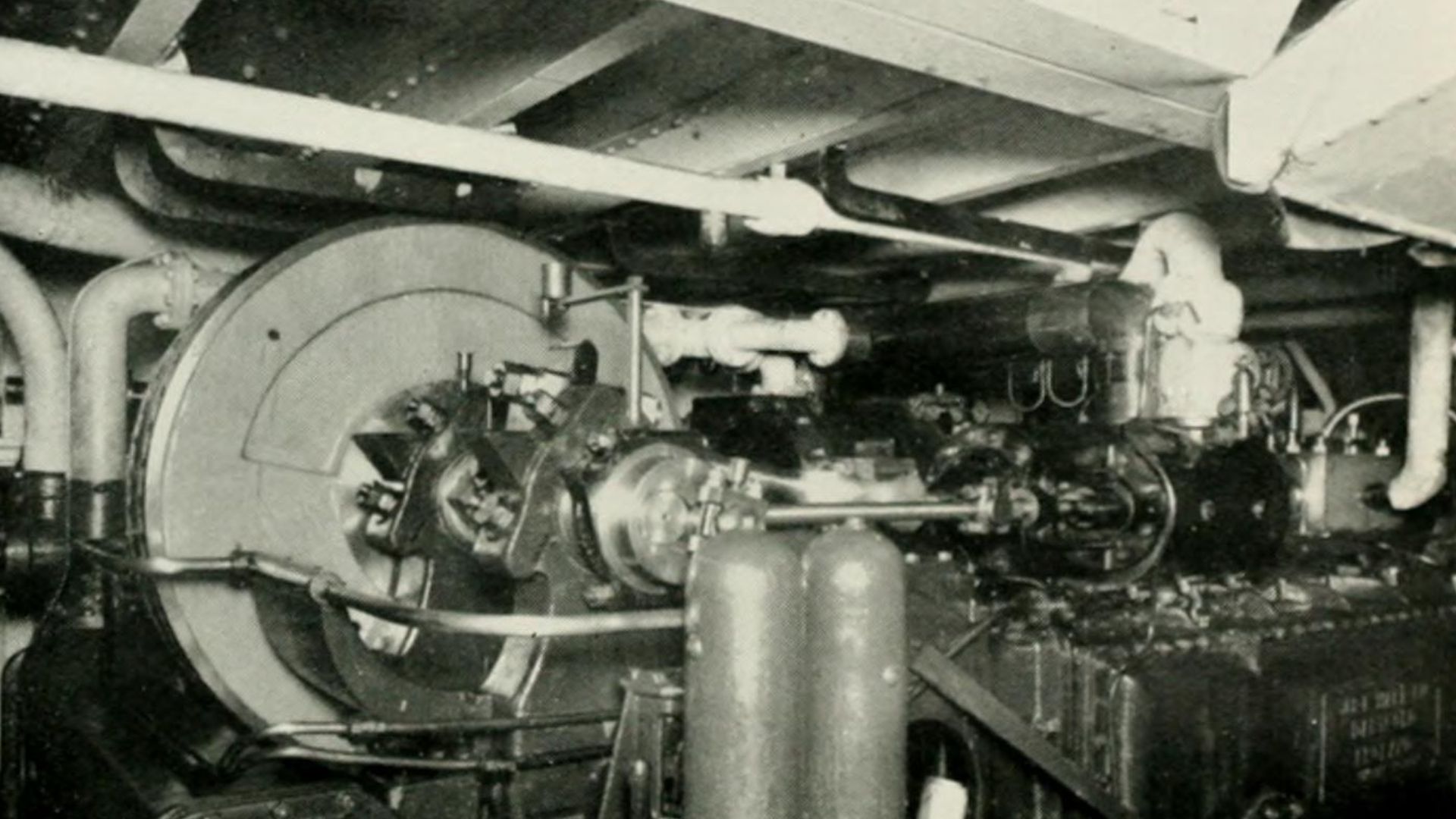
The Reciprocating Engines Remain Intact On The Ocean Floor
Twin reciprocating steam engines still stand upright, each roughly four stories tall. These triple-expansion engines powered the port and starboard propellers. Footage shows remarkable structural integrity despite corrosion, pressure, and more than a century of deep-sea exposure.
 Robert Welsh (died 1936), Wikimedia Commons
Low-Pressure Turbine Located Within The Wreck
The Parsons low-pressure turbine formed part of the ship’s propulsion system, using exhaust steam to supplement the reciprocating engines. While debris-field photography shows turbine-related components on the ocean floor, the turbine engine room itself remains largely inaccessible, limiting precise documentation of its current condition.
 Internet Archive Book Images, Wikimedia Commons
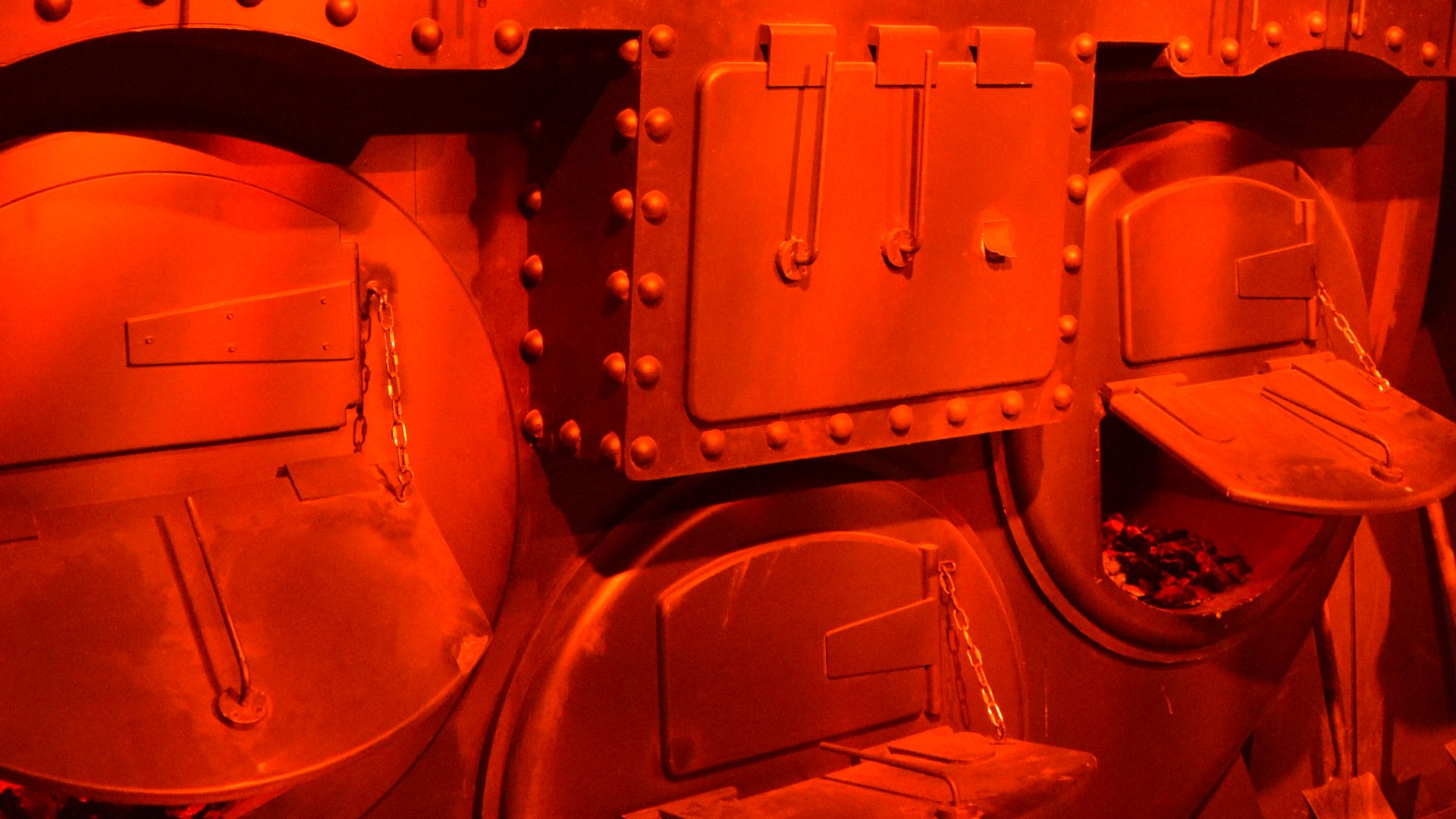
Boiler Rooms Show Evidence Of The Final Moments
Video footage reveals collapsed bulkheads, scattered firebrick, and displaced boiler sections across the debris field. These configurations indicate that boilers tore loose when the hull fractured to preserve physical evidence of the violent breakup during Titanic’s final descent.
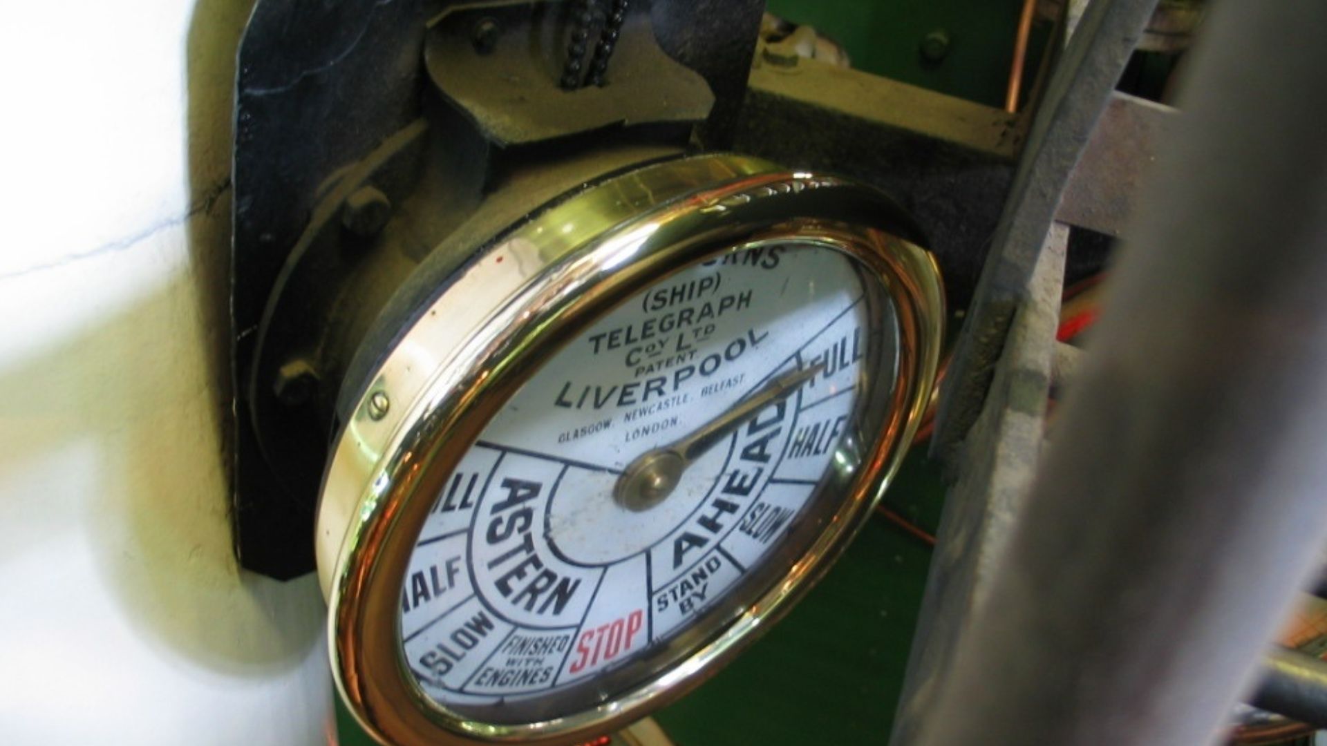
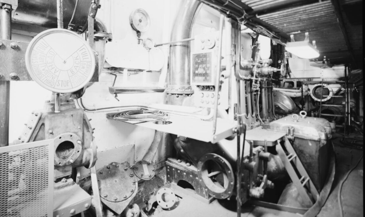
Did The Engines Go “Full Astern”? What The Evidence Shows
Brass engine order telegraphs survived the sinking and have been documented, too. Survivor testimony and engineering records indicate Titanic’s engines were briefly ordered “Full Astern” after the iceberg strike, but telegraph indicator positions on the seabed cannot reliably preserve that command.
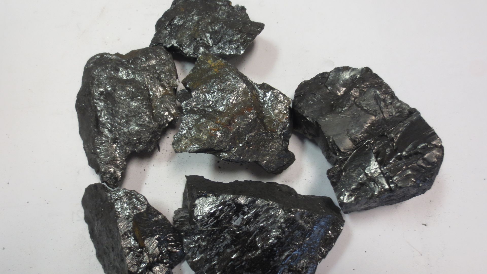
Welsh Coal Lies Scattered Across The Debris Field
Welsh coal spilled from ruptured bunkers during the breakup and is scattered across the debris field, particularly near boiler room remains. ROVs and submersibles have documented coal in distinct patches and layers rather than continuous carpets, with deposit depth varying by location and disturbance.
 Amcyrus2012, Wikimedia Commons
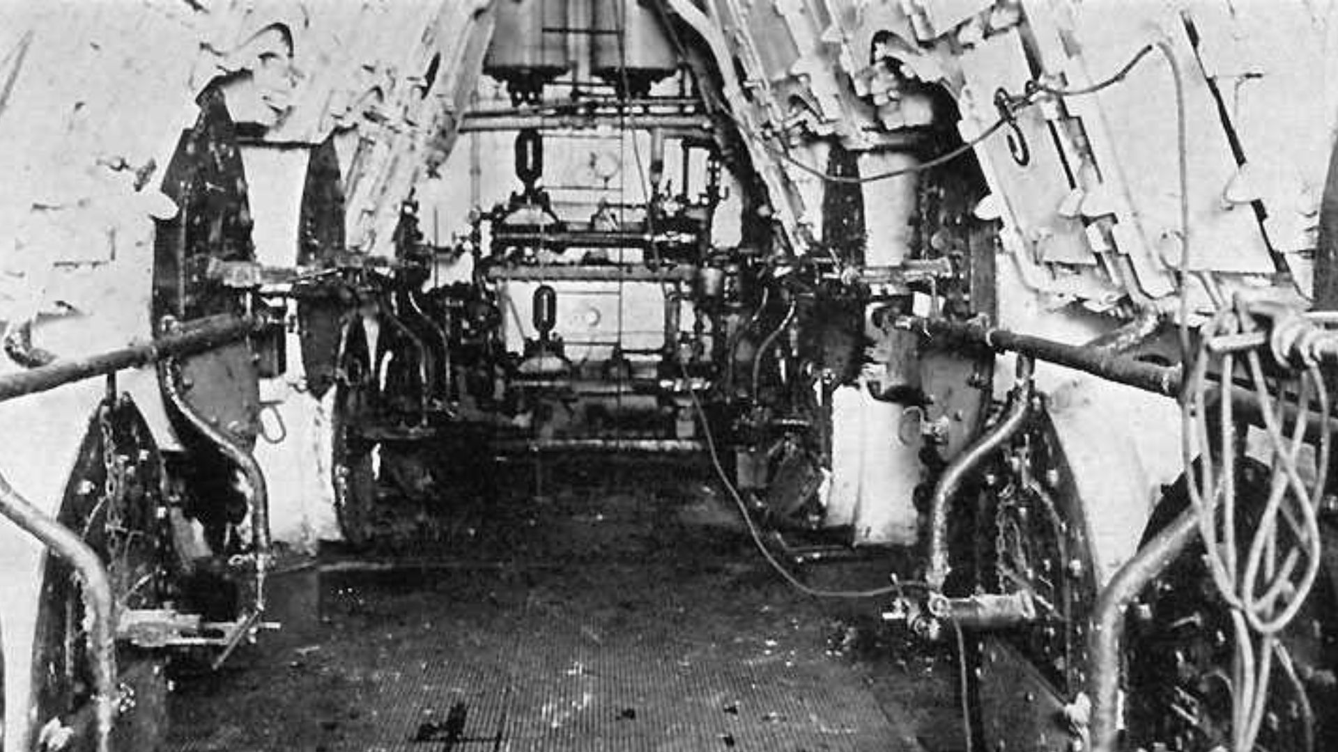
The Center Propeller Shaft Broke During The Sinking
The drive shaft linking the low-pressure turbine to the center propeller shows damage consistent with severe stress during the Titanic’s breakup. Wreck surveys document broken machinery and shaft-related debris, but corrosion, collapse, and sediment obscure visibility, preventing confirmation of a clean fracture into two distinct sections.
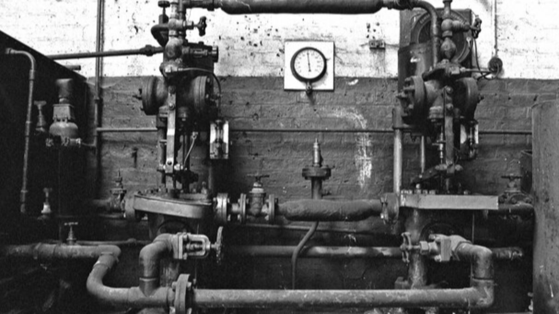
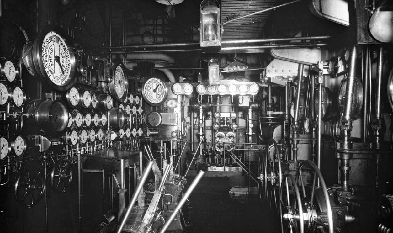
Pressure Gauges Reading Remains Inconclusive
Engine-room instruments, including pressure gauges, have been documented, though corrosion has rendered their readings unreliable. Survivor testimony and engineering records confirm that the boilers were operating during the sinking, but today's gauge needle positions cannot be used as evidence of steam pressure or operational status at the moment flooding began.
 HARTLEPOOLMARINA2014, Wikimedia Commons
Starboard Engine Room Entrance Shows Structural Collapse
ROV footage documents deformed watertight doors and twisted frames at the starboard engine room entrance. Wreck experts caution that this damage may result from hull breakup forces and long-term corrosion rather than direct inward buckling caused by rushing seawater, making the exact collapse mechanism difficult to determine.
 Lowe, Jet, creator, Wikimedia Commons
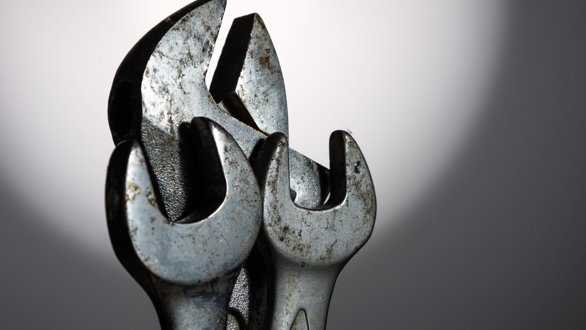
Engine Room Tools Lie Scattered, Origins Unclear
Expeditions have documented tools like spanners and valve keys scattered throughout the engine room areas of the wreck. Sediment movement, hull collapse, and debris shifts over more than a century prevent determining where the tools were originally dropped or whether they reflect emergency repairs rather than routine engine-room work.
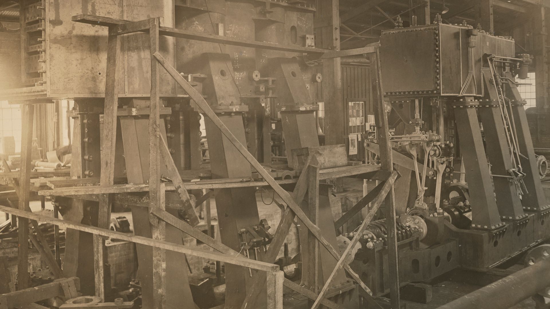
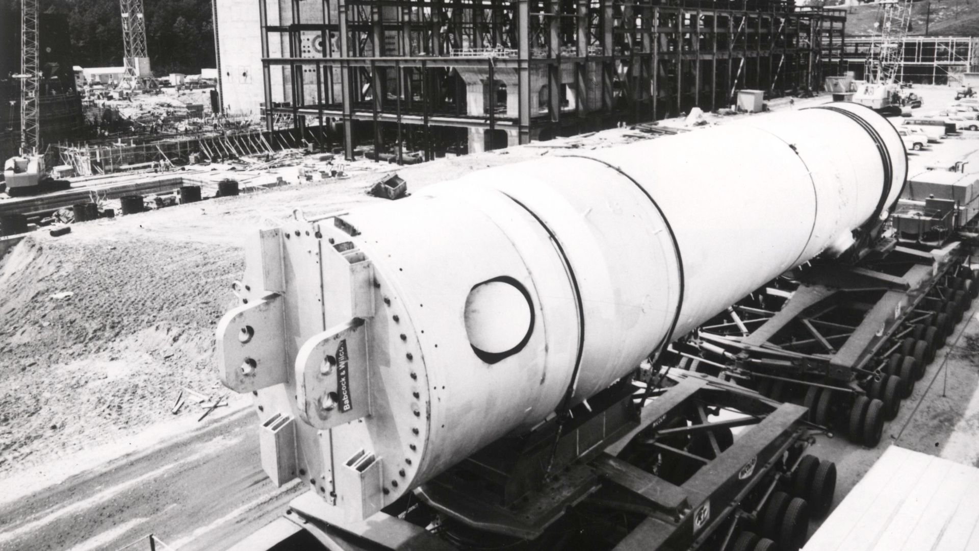
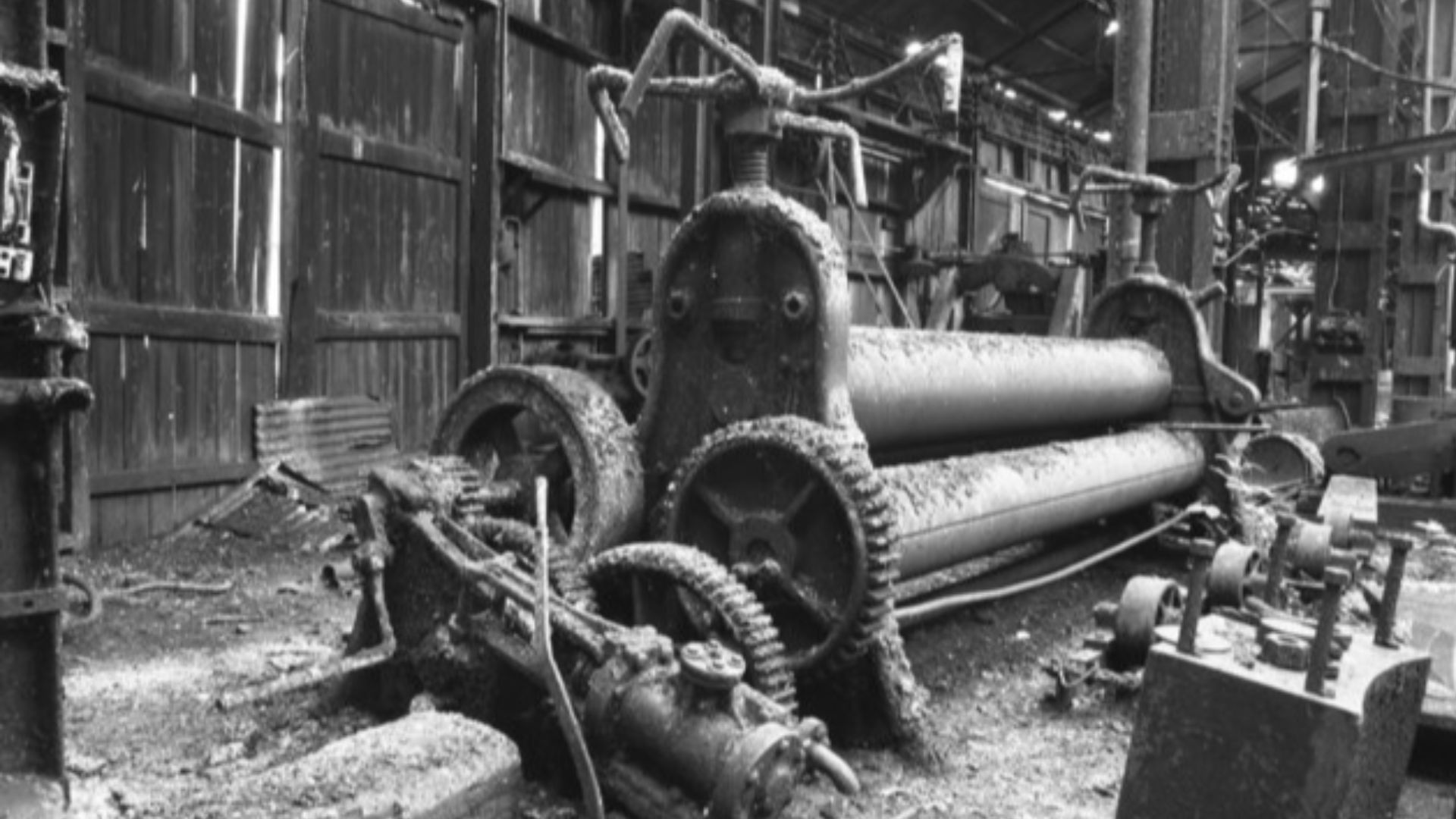
Triple-Expansion Engines Ranked Among The Ship’s Heaviest Machinery
Titanic’s two reciprocating triple-expansion steam engines each weighed about 720 tons, with their massive bedplates adding roughly another 195 tons apiece. While extremely heavy, neither the engines nor their foundations individually exceeded 1,000 tons, though their combined mass contributed to their relative stability during the breakup.
 Unknown authorUnknown author or not provided, Wikimedia Commons
Condenser Components Identified Within Engine-Room Debris
Surface condensers beneath the waterline used mixed metals to condense exhaust steam during normal operation. Submersible surveys have documented condenser-related pipework and debris on the wreck, though corrosion patterns observed on these components cannot be conclusively identified as galvanic in origin from available imagery.
 Ferguson Brothers Ltd., Wikimedia Commons
Stoker Tools Documented Near Boiler Room Wreckage
Expeditions have documented shovels and other coal-handling tools scattered within boiler room debris areas of the wreck. While stokers worked the furnaces until flooding rendered conditions untenable, sediment movement and debris shifts over time preclude using present-day tool locations as evidence of their final actions.
 Francis Dodd, Wikimedia Commons
Electrical Generator Remains Identified In The Stern Section
The Titanic was equipped with four steam‑driven electrical generators located in the stern, supplying power for lighting and wireless systems during the sinking. Wreck surveys have identified generator-related debris in this area, but collapse and fragmentation prevent confirming intact housings, couplings, or continued connection to drive mechanisms.
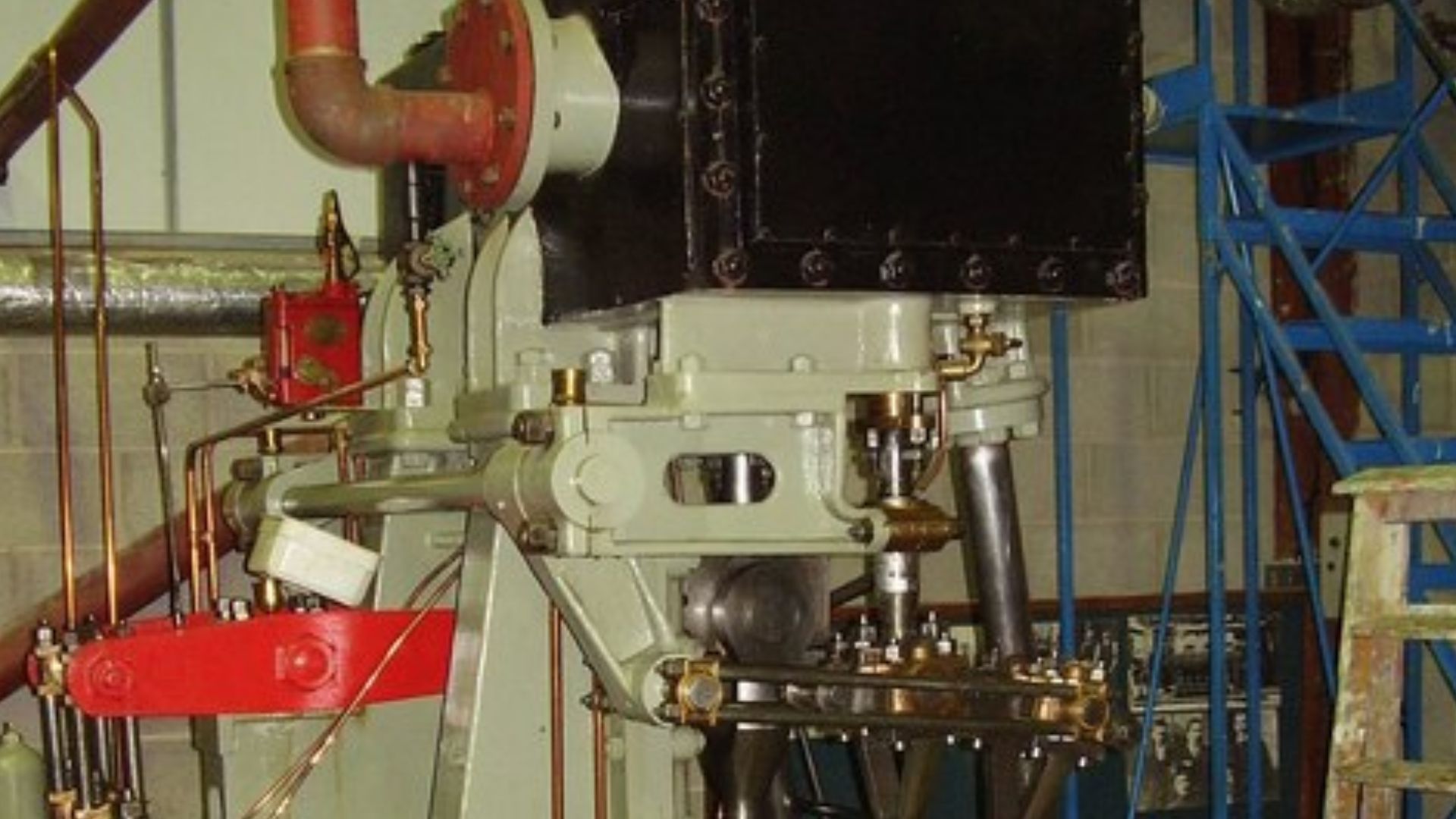
Cylinder Head Components Documented On The Engines
Expeditions have documented the high-pressure engines, including cylinder-head components, which now exhibit extensive corrosion and structural degradation. Even though these engines once operated at pressures exceeding 200 PSI, wreck imagery does not support identifying rupture patterns or damage caused by thermal shock from seawater exposure.
 Ashley Dace, Wikimedia Commons
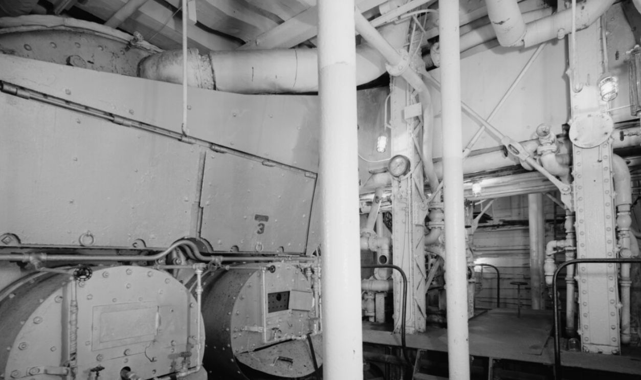
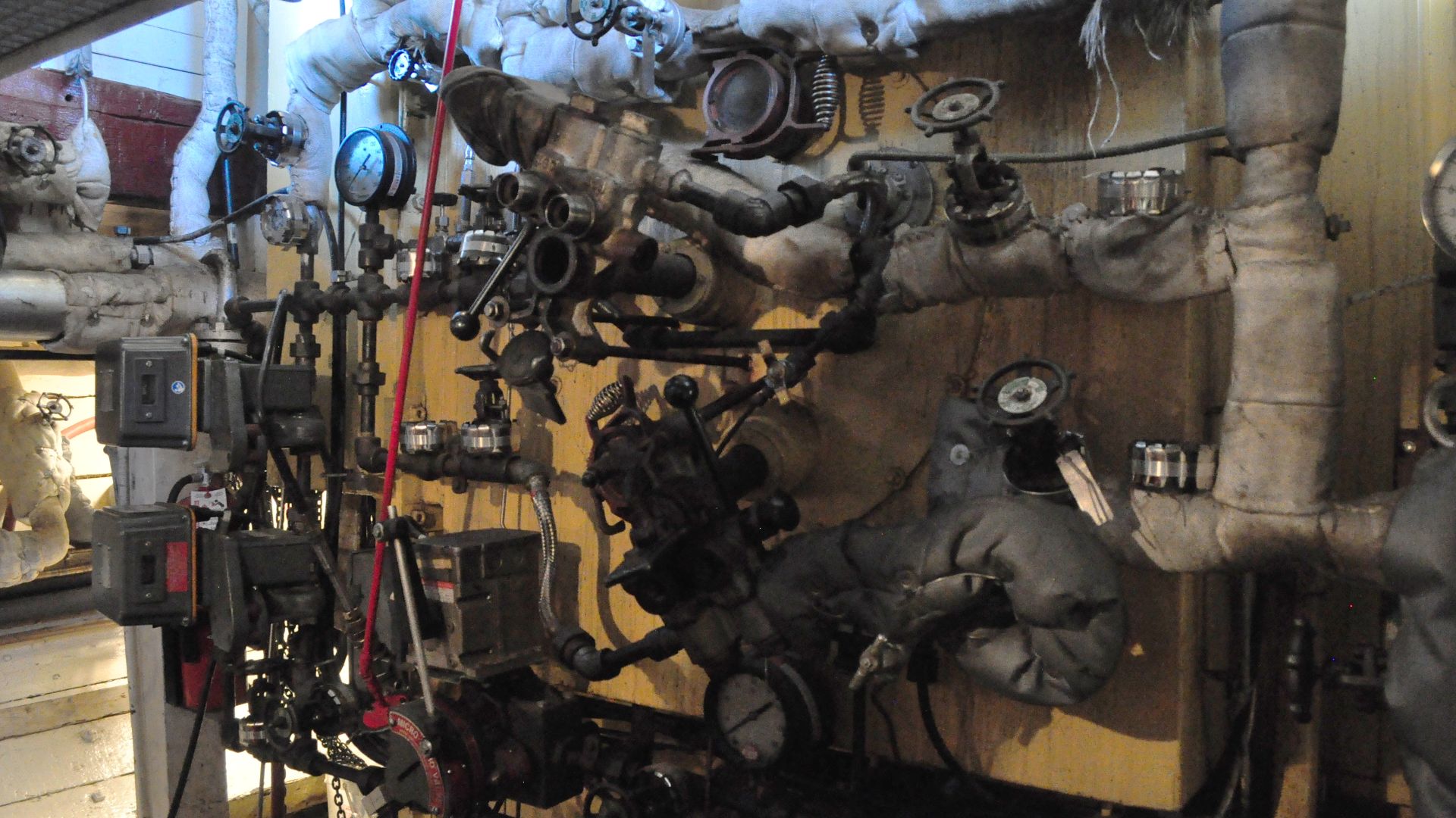
Boiler Feed Pump Machinery Documented Near Engine Areas
The Titanic was equipped with centrifugal boiler feed pumps near the reciprocating engines to recycle condensate back into the boilers. Wreck surveys have documented pump-related machinery in engine-area debris, but corrosion precludes confirmation that the pumps remain mounted in their original working positions.
 Chris Allen , Wikimedia Commons
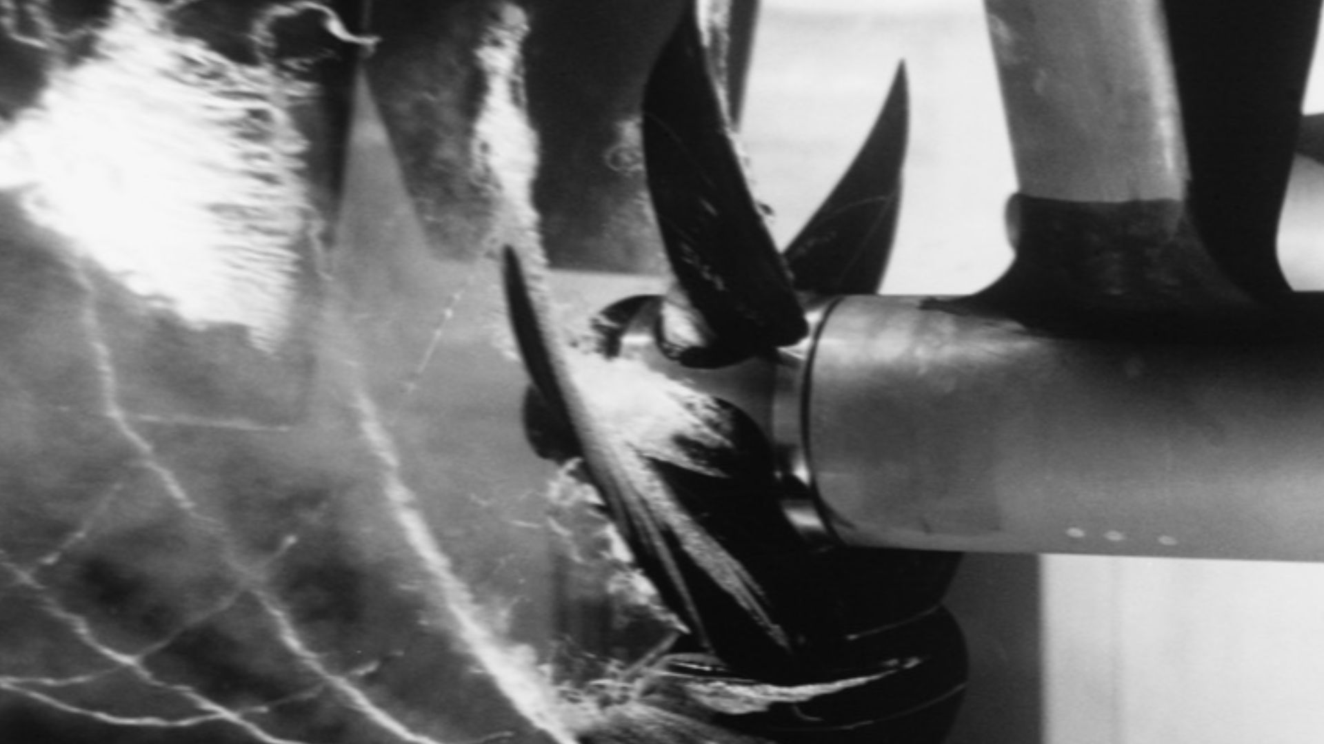
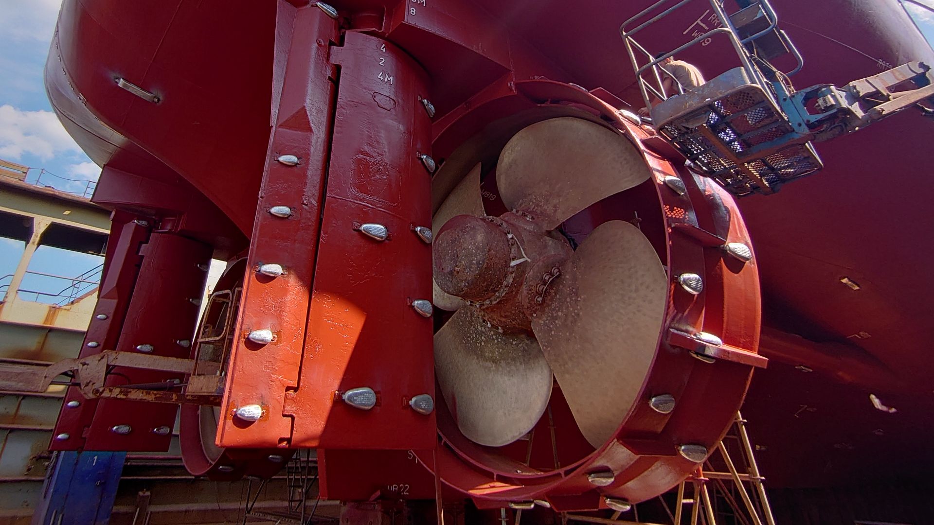
One Propeller Partially Buried In Seafloor Sediment
Titanic’s stern struck the seabed with heavy force, leaving the port propeller partially embedded in sediment. The starboard propeller remains visible above the seafloor. The center propeller lies deeply buried, roughly forty feet in mud, and remains unseen. The wing propellers measured 23 feet 6 inches, and the center measured 17 feet.
 Kleiner Stampfi, Wikimedia Commons
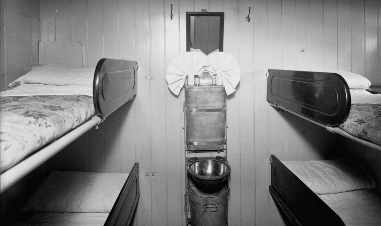
Cabin Locations Recorded Historically, Not Confirmed At The Wreck
Titanic’s senior engineering officers had private cabins on the F Deck, and junior engineers and crew occupied shared quarters elsewhere in the ship. Submersible surveys have documented brass fittings and interior debris on the wreck, but no authoritative expedition has identified personal effects or confirmed cabin locations by camera.
 Bedford Lemere & Co, Wikimedia Commons
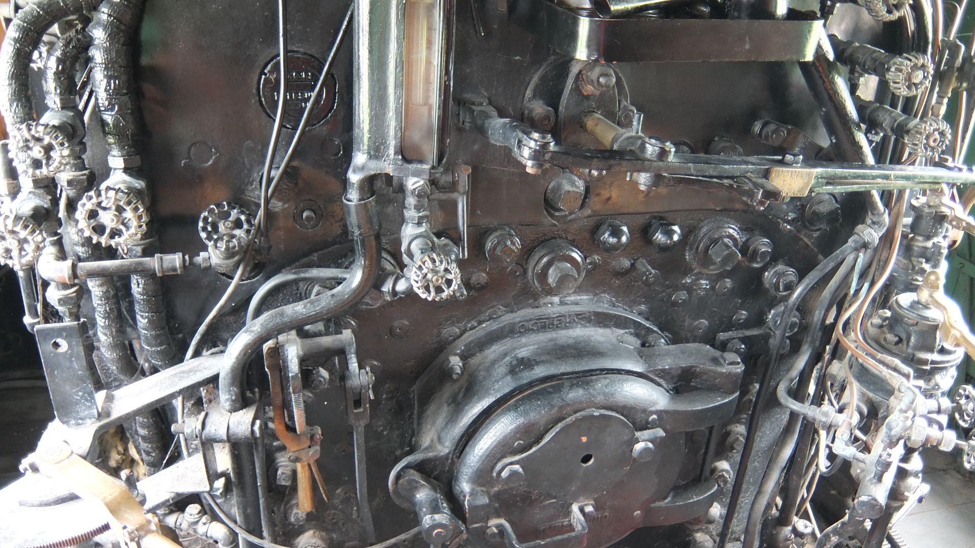
Valve Wheels Documented In Open Positions
Wreck footage has documented valve wheels in open positions within the Titanic’s engine-room areas. While engineers are known to have managed steam systems during the sinking, corrosion and mechanical displacement make it impossible to determine whether these valves were deliberately turned during the emergency or later shifted by damage to the wreck.
 Bedford Lemere & Co, Wikimedia Commons
Ash Ejector Systems Listed In Design
This vessel used steam-powered ash ejector systems to clear furnace ash and reduce manual labor in the boiler rooms. Surveys of the wreck have recorded boiler structures, coal deposits, and surrounding debris, though identifiable ash ejector components have not been clearly distinguished within the remains.
Watertight Door Components Observed In Boiler Room Areas
Titanichad 12 hydraulically operated watertight doors serving the boiler and engine rooms, several of which were successfully closed during the sinking. Wreck footage shows distorted door frames and mechanisms in mid-positions. We have no idea whether these doors failed to close during the disaster or were later deformed.
Firebox Grates And Ash Pit Debris
Scotch marine boilers relied on cast-iron fire grates to support coal beds during combustion, with operating temperatures reaching extreme levels under normal service conditions. Wreck footage has documented grates and boiler debris within ash pit areas, although their present condition cannot be attributed specifically to heat rather than breakup forces or seabed impact.
 shankar s. from Dubai, united arab emirates, Wikimedia Commons
Steam Pipe Damage
Wreck surveys and scan footage show mangled steam piping, collapsed decks, and twisted valves consistent with severe structural stress during hull separation. The damage appears chaotic and compressive rather than cleanly fractured. These pipes once carried high-pressure steam.
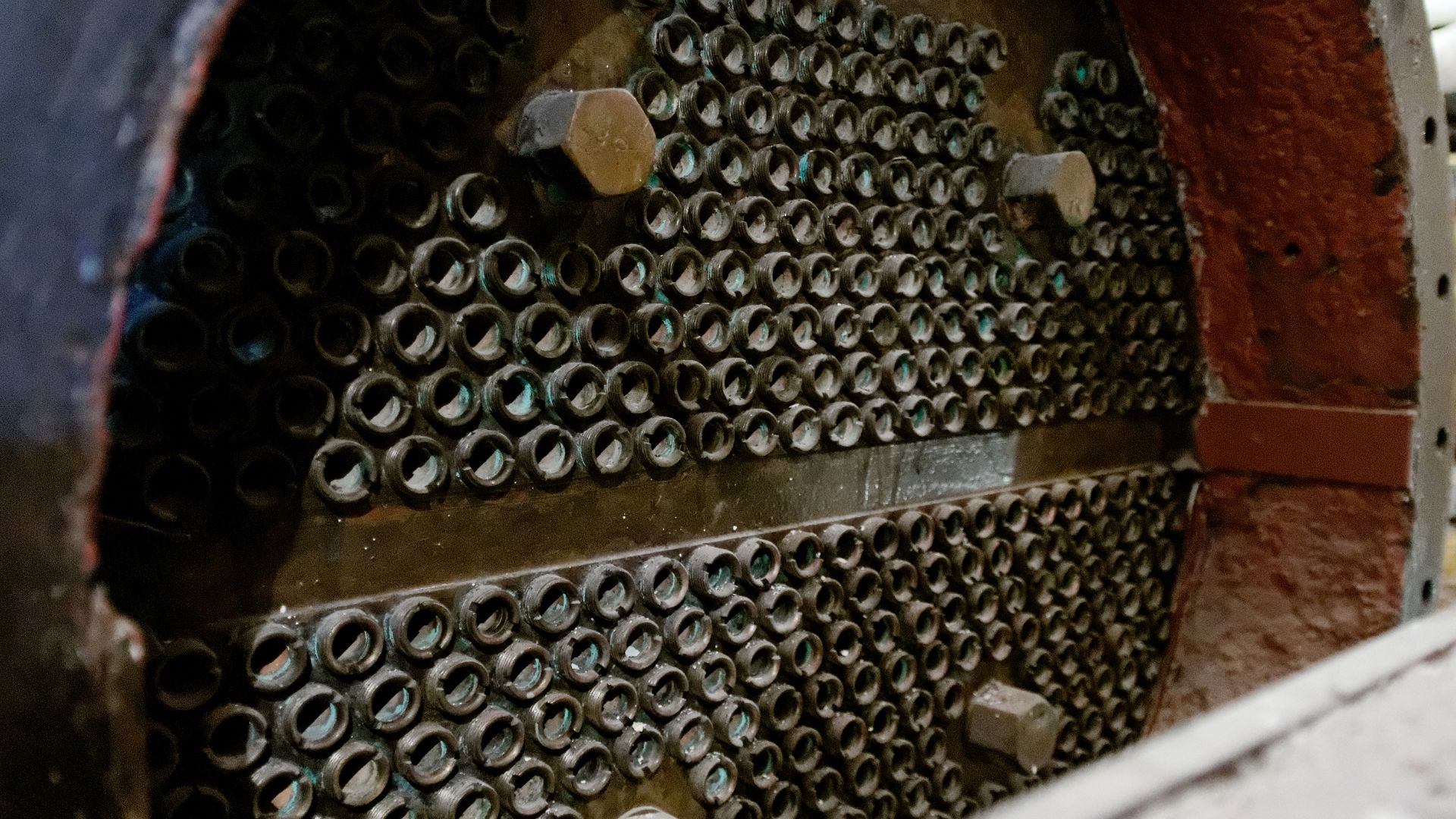
Boiler Plates Show Riveted Construction Methods
Riveted steel boiler plates remain identifiable across the debris field. Camera close-ups show overlapping seams secured by thousands of rivets, driven hot during construction. This labor-intensive process created pressure-resistant vessels vital to steam propulsion.
 Chris Allen, Wikimedia Commons
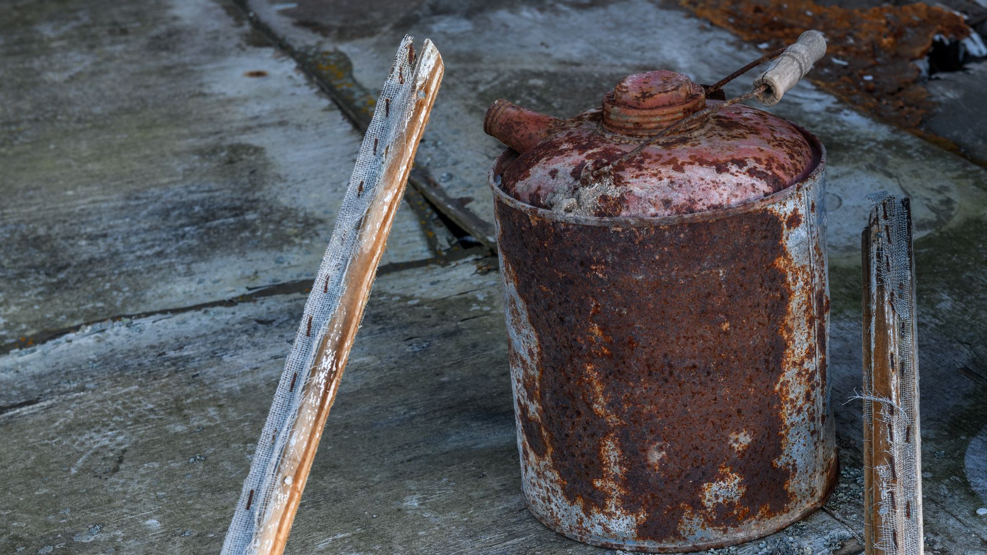
Lubrication Equipment Found In Engine-Room Debris
Expeditions have documented hand-pumped lubricating oil cans and related maintenance equipment within engine-room debris areas of the wreck. These tools were used to apply heavy mineral oil to bearings and valve components during normal operation.
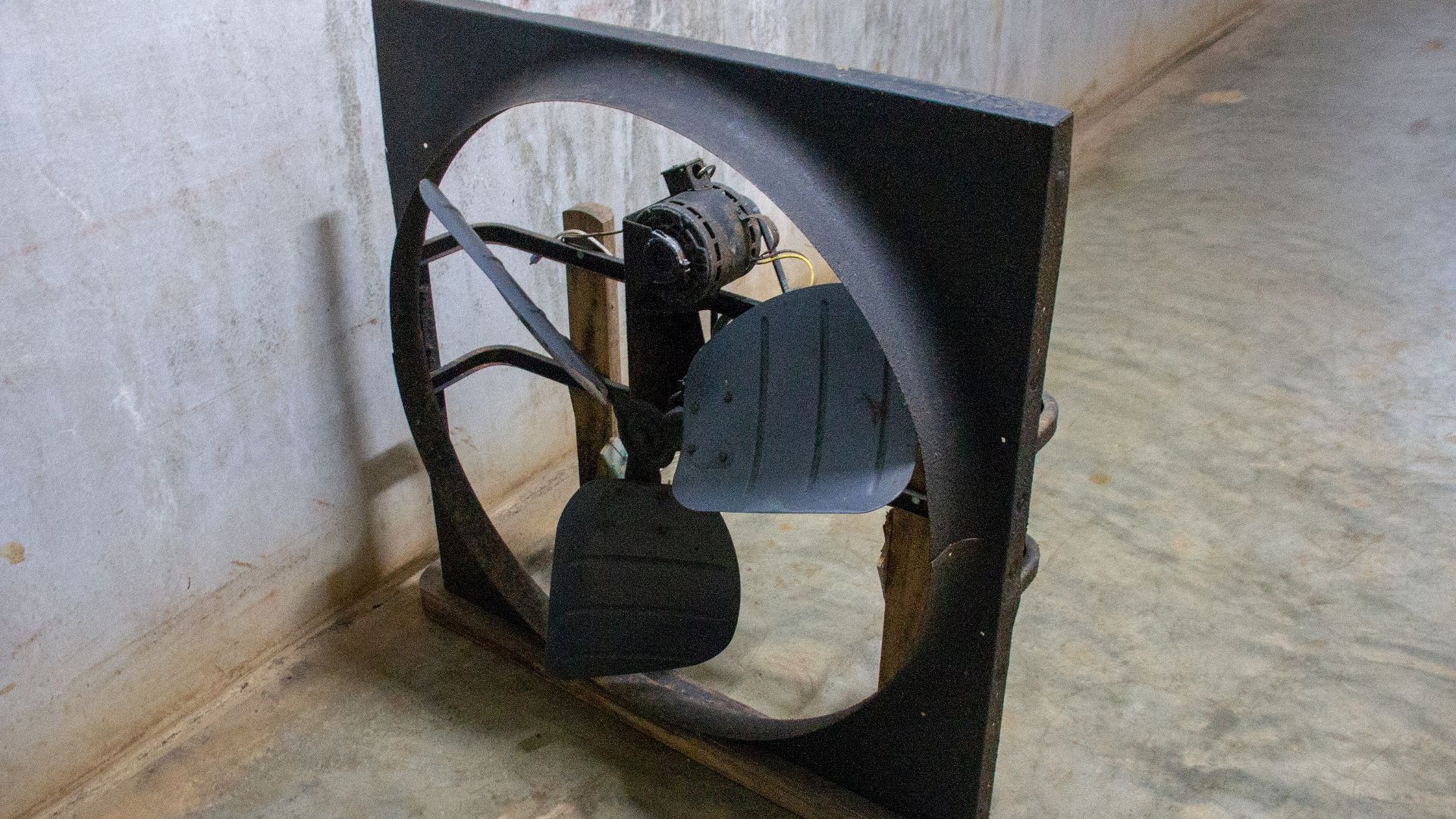
Ventilation Fan Components
Ventilation systems supplied combustion air to the boilers through electric and mechanically driven fans housed in dedicated shafts. What the surveys have documented is heavily corroded ventilation-related structures and debris. No evidence has identified intact forced-draft fan impellers preserved within the shafts; sediment obscures these areas.
 Photograph by Mike Peel (www.mikepeel.net)., Wikimedia Commons


